
This is a PIC microcontroller project I did some time ago which turns my computer’s hard drive LED into a more interesting 10 LED bargraph display.
One afternoon, I was looking for a simple microcontroller project I could whip-up just for fun. I knew that I would soon be ordering a new computer case, so I figured that I might as well create some kind of display to enhance the appearance and/or functionality of the new case. But what to improve?
I settled on the hard drive LED. On all computer cases I’ve seen, the HD LED is just a single, boring light. Yeah, maybe it comes in blue or purple on your fancier cases, but it’s still just a boring light. I wanted something a bit more flashy and dynamic. For years, I’ve had a Radio Shack 10 segment LED bargraph floating around in my parts box, since I’m a nerd, I naturally love blinking LEDs (das blinkenlights), so the LED bargraph HD light idea was born!
I reached for my trusty Microchip PicStart Plus programmer, a perfboard, some wire, and got to work!
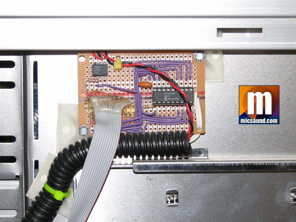
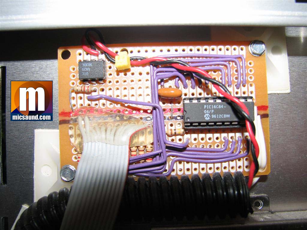
I first got the LED unit, socket for the PIC16C84, and basic wiring done on the perfboard. The clock is provided by a 4MHz ceramic resonator and for good measure, I put an opto isolator on the input from the motherboard LED connector. I figured that the optoisolator would present a similar load to the mobo’s drive circuit since it’s just a very small LED in essence.
Next, I started to work on the software. I normally do most of my microcontroller work in the native PIC assembler, but this seemed like a good project to try a compiled language since the project is not timing critical. The compiled language let me not worry about counting higher than 255 or messing with multiple registers to assemble long delays. I had been hearing some good talk about JAL (Just Another Language) which targets these lower to mid-range PIC devices, so I figured I’d give it a try. It’s a GPL project and is free.
JAL was very easy to use, especially for this simple project. It made working on the timings of the lights very easy, which was important as the speed of the rise and decay of the LEDs is critical for the finished result to look cool. The code is basically an accumulator type setup where the HD signal from the mobo is polled and if it’s on, a number is added to the internal counter. If it’s off, a number is subtracted. In between polling, that counter value is divided to determine how many LEDs on the bargraph to light.
I had to do a bit of tweaking for aesthetics, such as making the first LED very “sensitive” (it lights immediately) so that you can see the minor blips that are common under a modern operating system. I also made the 10th LED very fast to turn-off or else the display would appear to lag since it is pretty common for the indicator to peg at LED 10 and decrementing the counter like the other LEDs would take too long.
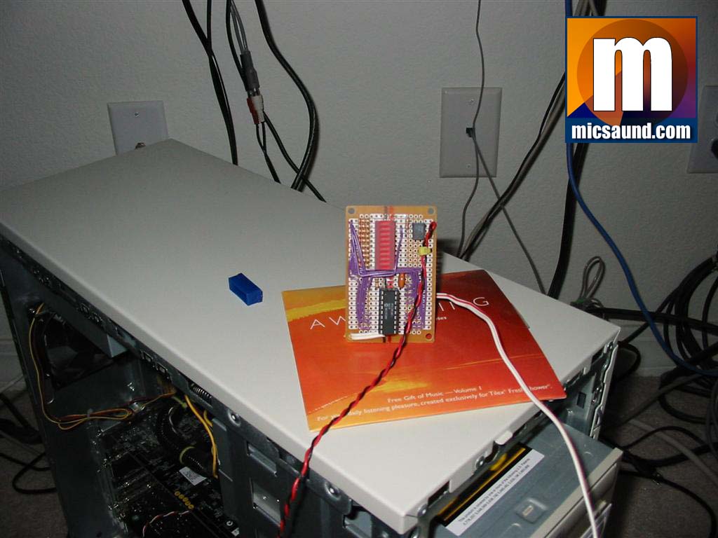
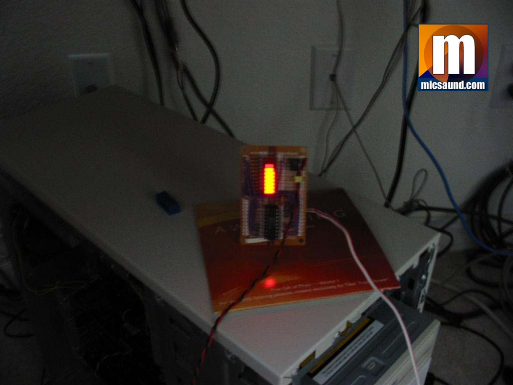
Here, you can see the prototype with the LED unit soldered to the perfboard. There is a power and ground (the white wires) and the connection to the motherboard LED output (red and black). I know – those coloring schemes for the wires are messed-up, but the red/black wire was cannibalized from an old case since it already had the pin header on it.
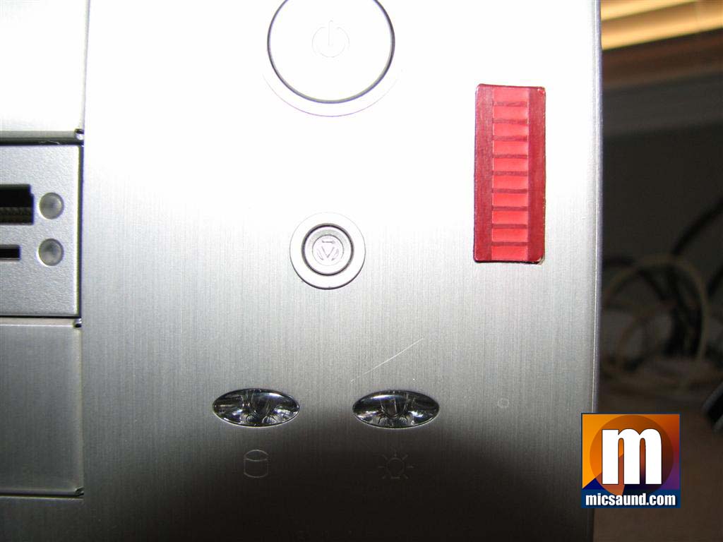
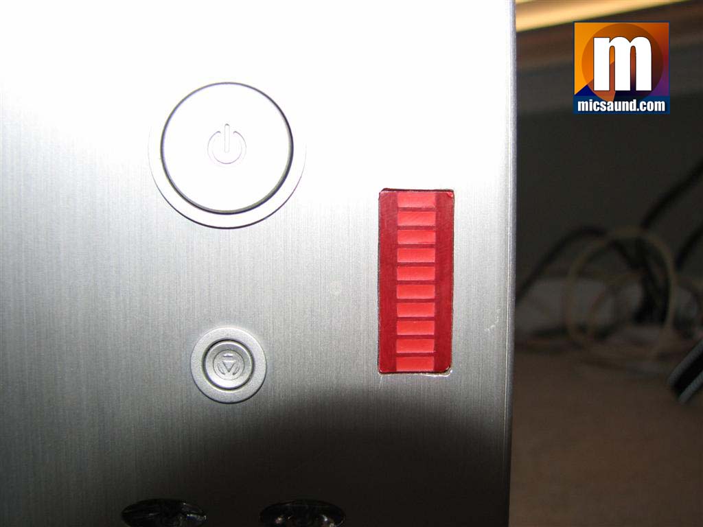
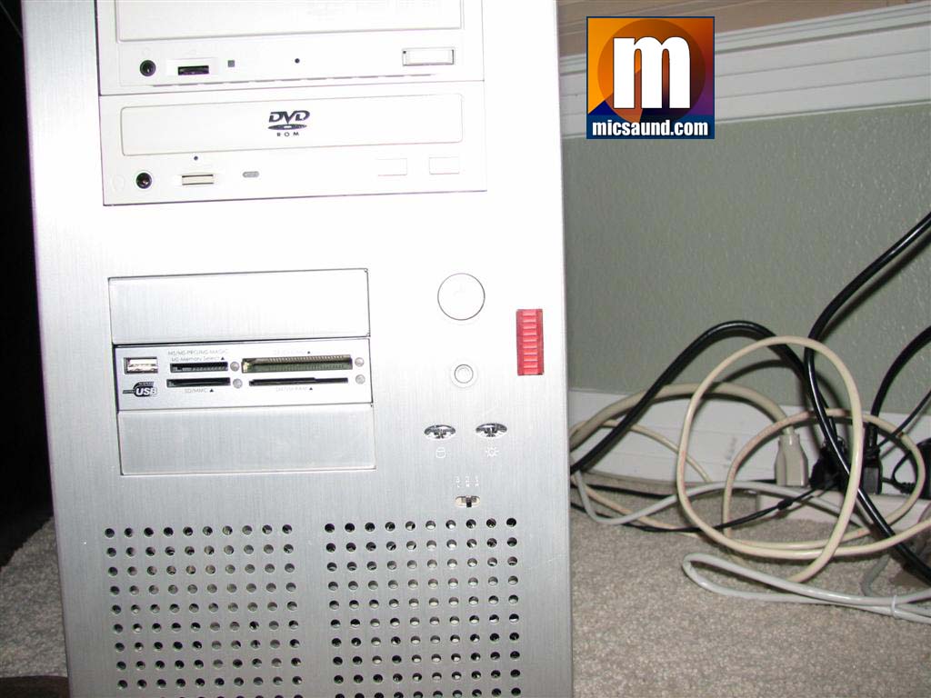
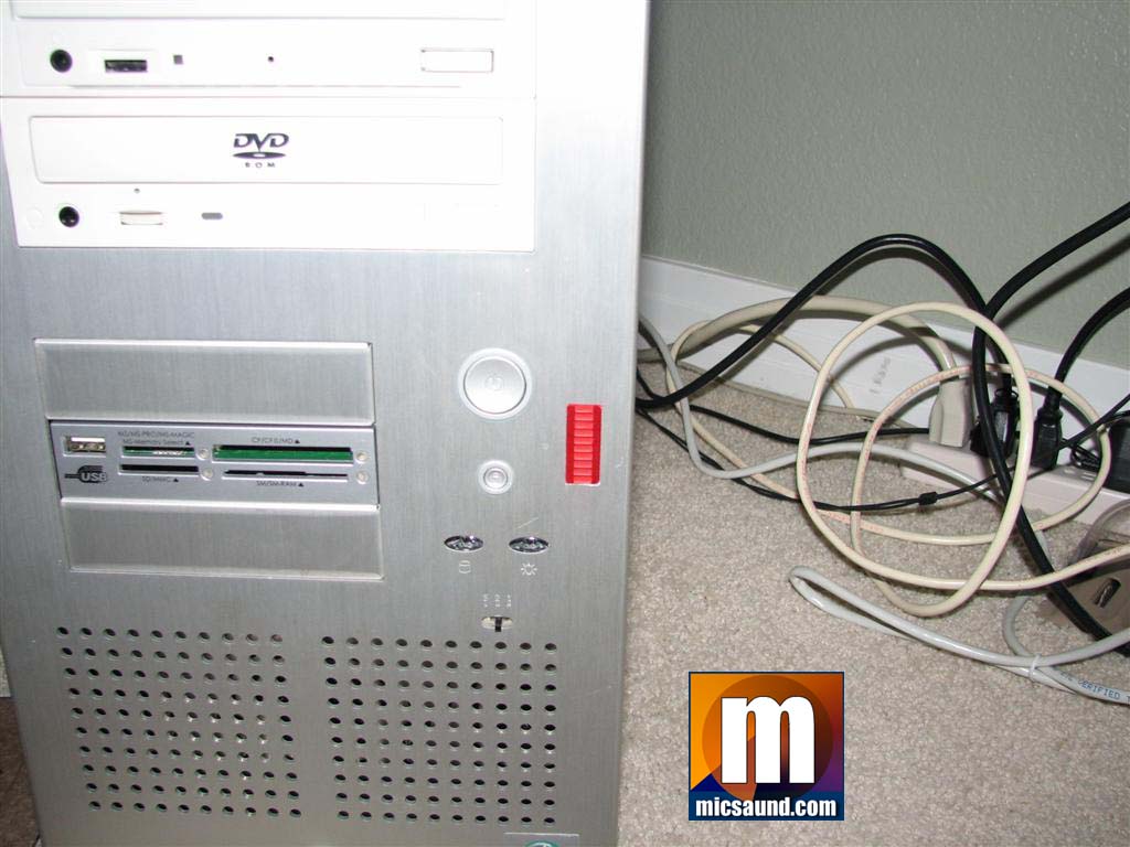
Now that I had the project fine-tuned the way I wanted, it was time to install it in my new aluminum case. I carefully used a nibbler to create the rectangular hole for the bargraph to emerge through. I desoldered the bargraph from the board and used another piece of perfboard to make a landing board for the LEDs and a ribbon cable which connects the control board to the display. This display board was carefully mounted on the backside of the aluminum faceplate so that the front of the LEDs are flush with the front of the case. Doing this cutting on my new case (the most expensive case I’ve ever bought) made me very nervous, but it turned-out good.
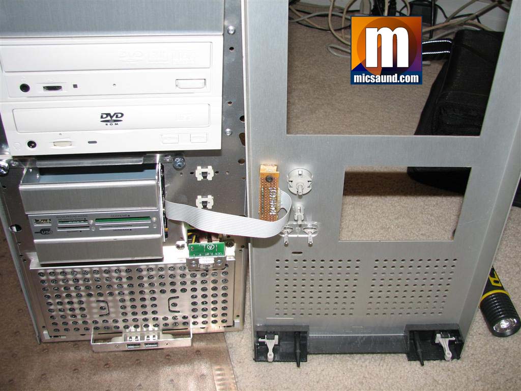
Next, I mounted the control board. I found a place in the case where the removeable motherboard tray would not hit the project but where it was still close to the front panel.
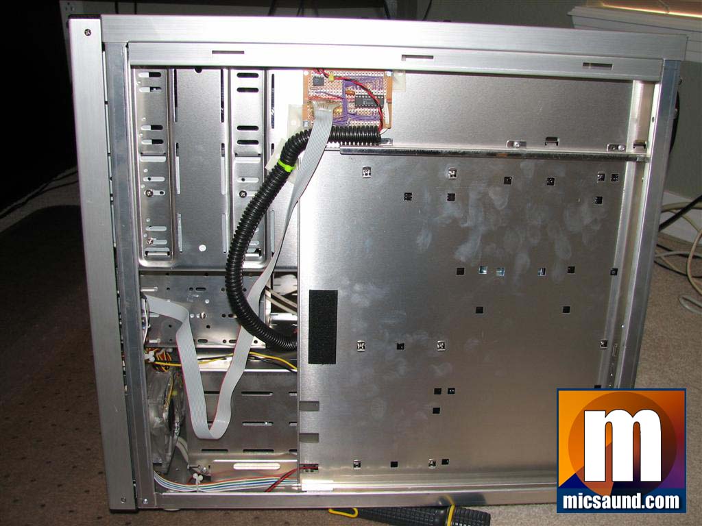
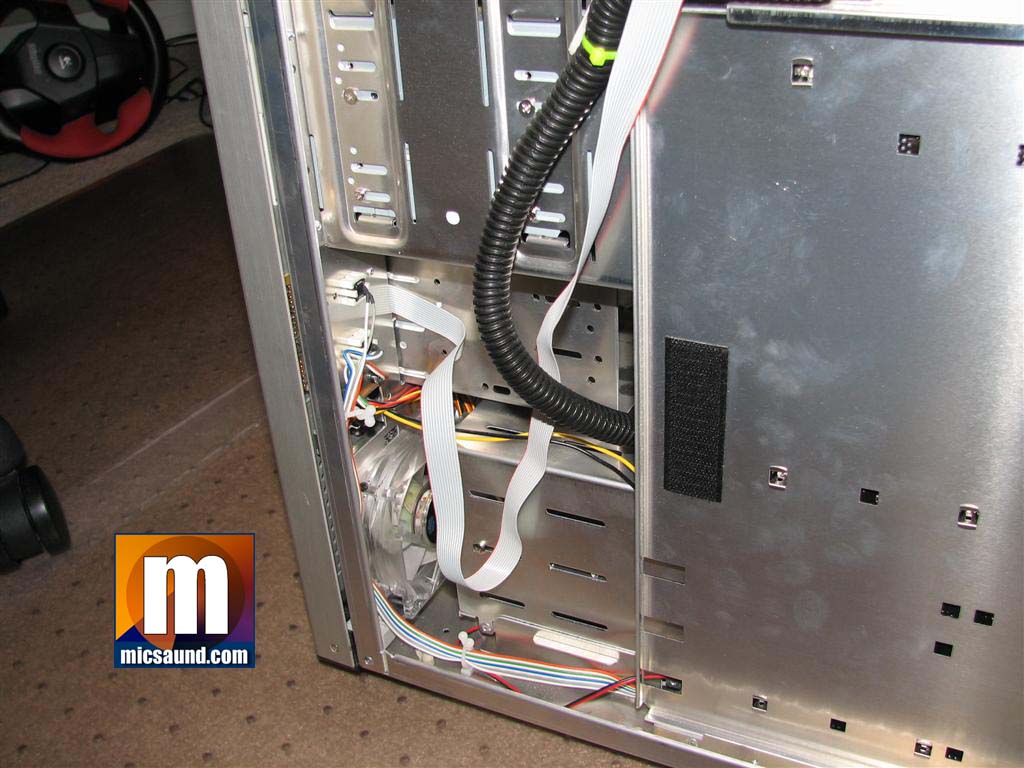
Connecting the two boards was easy with a piece of spare ribbon cable. I spooged both ends with some hot-melt glue to prevent the thin wires from getting flexed at the board. The ribbon cable comes-out right next to the floppy drive cage, which is removeable and makes it very easy to get the project out if needed. The PIC microcontroller has enough drive capacity that direct driving the LEDs across the ribbon cable provided no issue whatsoever. I wrapped the power connection in some black plastic loom to make it look better. There is a standard large floppy power connector on the other end for easy connection to the system’s power supply.
I did not bother with in-circuit programming, so should I ever want to adjust anything, I’ll have to pop the chip out of the socket and into the PicStart Plus to re-program, but I don’t expect that I’ll ever have to adjust anything as I’m quite happy with the effect of the pulsing bargraph.
Using the PIC PIC16C84 microcontroller made this project very simple, as PICs often do. With only 35 instructions (typically), they are powerful, easy to learn, cheap, and above all, useful. JAL was a breeze to learn and use, at least in the context of this project. Overall, I’m very pleased with the outcome. If I had it to do over again, I might try using a FPGA (Xilinx or Altera probably) as I’ve been wanting a project to learn gate arrays. However, since this one is complete, the FPGA learning will have to wait for the next surge of motivation and creativity!
Oh yeah – you were hoping for a video, huh? 😉
Bargraph HD LED video
And finally, a short video showing the bargraph in action! It’s in Xvid format so you’ll need the appropriate decoders.
EDIT:
I dug-up the Microcontroller LED hard drive light source code. Please see the README.txt file for a little info.
Here are some useful books if you’re curious about PIC microcontrollers and designing electronics and other gadgets with them:


Very nice. Could you provide a schematic and/or any code?
@mrklaw:
I will see if I can dig-up the JAL code from my old development machine. It has been a couple years since I did this project and I *think* I still have the zip of the code.
As for the schematic, I just free-wheeled it. Bad practice, I know 😉 It’s very simple – basically, one 8-bit port and 2 bits from another port are directly connected to the LEDs. The necessary current-limiting resistors are in-place as is the typical connection for a ceramic resonator on a PIC. The source code, if I can find it, should help explain things too. If there’s enough interest, I could try to draw-up a schematic, but I don’t have any EDA tools installed right now, so it might be rather hackneyed 😀
@CandyAddict:
Thanks for the link in Makeblog! I looked at my traffic numbers and was surprised until I saw your comment.
Mike
Another way to do this would be to use 11 op-amps (It’s not as bad as it sounds, since you can get them in multi-amp chips), with one set up as an integrator (to average the HD usage), and the rest of them as an ADC (string of resistors in series, with comparators hung off it).
Or, just skip the adc, and use a panel meter for that oh-so-trendy steampunk look 🙂
Hey, nice work with counting the pulses – what a great idea.
I’m sure we’ll see something like this in those flashy ‘fanbus’ controllers used to waste device bay space. Better visit the PTO office and get your name on the books 😉
If you dig up the source, I’d love to see it (if you dont mind).
Gordon
Nice effect. The video looks very good!
Source code is now available. Look for the EDIT line in the main post by the video 😀
Also, thanks for the great comments everyone! I’m glad that this is of interest.
Mike
Fun idea! I also need an excuse to fire up the Pic starter kit.
Also, it could be done purely analog with a transistor driving a resistor & cap charge fed into an LM3914, which will drive the 10 segment LED directly based on voltage. (The LM3914 is a 10 step comparator and LED driver for Vu meters) You might not even need the transistor, if you were careful about keeping the current and voltage charge low.
or a 3915 or 3916, if you prefer. I believe the 3915 is log scale, while the other two are linear. Can’t remember off the top of my head what the diff is between the 3916 and 3914…
You’re welcome! 🙂
brian
http://candyaddict.com
Yeah, I figured that an analog version of this would be fairly easy to implement, but alas, I’m a “digital guy” and try to stay in the comfortable binary world of 0v and 5v as long as possible 🙂
Mike
Actually, I’m more comfy in the digital side too, but the 3914/5/6 is just too damn nifty a chip for das blinkenlighten projects. The 4026, MM5450, ICM7228, IBM 7218 and ICM7225, MAX6960, 555/6/8, and the LM316 share a warm place in my heart for the same reason. 🙂 (and many of those chips are good for TTL->LED driving)
BTW, what did you use to cut the nice , clean SQUARE hole in your AL front panel? A nibbler, dremel, or ???
@Lars:
I first marked the dimensions I wanted to cut, although I drew the rectangle a bit small as it’s much easier to enlarge the hole rather than try to make it smaller 😉
A small hole was drilled to allow the nibbler’s jaw to be inserted into the panel to do its thing.
The hand nibbler is from Radio Shack. I just carefully nibbled my way around the markings I made until the hole was cut.
Once that was done, I used some small files to clean the edges and enlarge the hold as-needed. Note that when filing aluminum, the file’s teeth will become clogged with material and need to be brushed out with a wire brush. Fortunately, I did not need to do much filing as I was very careful with the nibbler.
I tend to avoid Dremel type tools whenever possible as I have a really hard time keeping the cutting wheels (or other bits) under control. Dremels are good for many things, but I think they are often over-used since so many times they are hyped as the “do it all” tool when they aren’t really the best option.
Hope that answers your question,
Mike
Very cool – nice to see the idea spreading around. I saw one like this last year sometime, but I don’t remember where, which prompted me to do a version too. Hey – imitation is the best form of flattery.
A couple of pics are at http://www.avrfreaks.net/index.php?name=PNphpBB2&file=viewtopic&t=35933&start=123
And a couple of (bad) video links are at
http://www.megaupload.com/?d=TESWY615
http://www.sendmefile.com/00314955
http://www.filefactory.com/get/f.php?f=bd0f42f9cbed6497f526a663
I have another two versions using an 8515 as well, but I’ve given them away. I didn’t take any photos unfortunately. These both used an 8×8 led matrix.
One was for an 8 drive raid controller, so you had 8 bargraphs of 8 leds each blinking away. The other was just an extension of the 2313 version, like a moving graph. Each update shifted the left column of leds over to the right one space, so it looked a bit like a traffic graph.
Dean.
Thanks for sharing, Dean – looks pretty cool. As you noted, those are some very irritating upload sites! 😀 I only got the sendmefile one to even work, which was naturally the last one I tried. You can try putfile.com or youtube.com for your other videos which are direct links to your videos without the 40 second artificial delays to study blinking ads “while the free download links are generated” (haha what a joke).
Mike
Have you ever been to ‘you tube’? they let you host videos there and you can hotlink them on your blogs. it’s really cool and you don’t have to bandwidth on the videos, cause its free.
I thought your idea here was really cool but, could you please provide some nice schematics ( wiring diagrams ) so i could build it too..???
Is that source code link up there the programming for this thing.??
Yes, the code provided is the programming code for this particular project. If you look at the readme in the zip + the code, the schematic will be pretty evident (I don’t have a schematic program to capture the circuit).
[quote]Yes, the code provided is the programming code for this particular project. If you look at the readme in the zip + the code, the schematic will be pretty evident (I don’t have a schematic program to capture the circuit).[/quote]
————————————————————————–
Well i download this:> ” Microcontroller LED hard drive light source code. ” and i read through the read-me file but i fail to see how there’s any schematics in it, Am i missing something here.??
I really don’t wanna sound rude, but, Where’s the schematics. ( Circuit diagram ) .??
That’s because I do not have a schematic capture program (as indicated in the text you quoted) and you need to utilize your electronics skills to deduce the extremely simple schematic. It’s very simple and a basic knowledge of connecting PICs and LEDs is all you should need combined with viewing the source code and what has been described on this page.
( quote ) That’s because I do not have a schematic capture program ( end quote )
So whats a schematic capture program.? Why would you need it.?
Couldn’t you just use something like MS-Paint to draw out a simple picture of what goes where.? Like draw a rectangle to represent the main chip, label it, and draw skinny lines to show the wires.
To show resistors and such just make that part of the skinny line “broad” ( Fatter ) then label that.
( quote ) you need to utilize your electronics skills to deduce ( end quote )
My electronics skills aren’t that good to the point that i could think my way through it, To be able to know where everything goes without being told beforehand.. Thats the reason why i ask..
So, with such very little knowledge of electronics like connecting LEDs, do you have a PIC programmer to program the microcontroller? Without that, and I’d think that most people who have such a device already know how to connect LEDs, you will not be able to build this project as I have described it.
A schematic capture program is a program that lets you build nice-looking schematics with the concepts of wires, device instances, etc. MS Paint would work but that would be like painting a house with a 1 inch brush – it works, but it’s far from worthwhile. See the Wikipedia entry or a PDF from Cadence for more.
As I mentioned in comment #3, I did this project a couple years ago and do not have any design documents available other than what’s already been posted — I “winged it” off the top of my head. I was lucky to be able to find the source code when somebody (politely) asked, and I made that available. Unfortunately, that’s all I have. Here is some info on connecting LEDs to a PIC which you may find useful. Remember, V=IR is the secret. Also, you might want to check-out some of the books I linked to if you are very new to electronics and/or interfacing with PIC microcontrollers.
Spectacular.. absolutely… spectacular! The video of it was great, as it basically showed me exactly what I had hoped. Not just a simple ‘sweep’ everytime the drive accessed, but.. varying to different degrees as the drive access changed. Your choice in where to mount the controller board.. again.. brillinatly thought out. the choice of flex-wire tubing (like that seen under the hood of cars just much nicer and cleaner hehe.. was a great touch.. it gave it a clean yet ‘industrial’ appearnace. I have been looking for something to add to my case.. I am nor one for ‘flashy-all-show-and-cute-but-useless’, however, your project is just what I would consider ‘a perfect blend of ‘nice show and ‘informative/functional’
Excellent work..and hey, if you come up with any more great ideas like that, please share them..
Do you think there is anyway to implement this on a MAC???
Yep, I’m sure there probably is. This project is not hardware specific and will work with any computer/device that has an LED connection that pulses. I, unfortunately, don’t have a Mac right now, so I don’t know if they have a hard drive LED, but if so (or if your drive itself has the pins for it) you can hook it up.
Mike
Umm , So what happened to my comment..???
What so i’m not entitled to my opinion..??
This is great but really what you need is a bargraph displaying CPU % usage, and Network Activity %… or better, a multifunction one that displays in in to led digits 0-99, and can be configured whatever stat you want monitored
Really what I want is a hub with a network activity bargraph, that can be plugged in between your cablemodem and your router, and displays donwstream K and upstream K being used. I use to have a 10bt one with a simple bargraph, but lightning fried it.
http://www.freepcb.com/
That was hard to find ( role eye’s ) , Now can you provide a schematic for this thing..?
Uhh… don’t hurt yourself when you *roll* your eyes. That package does not make the schematics you’re in such dire need of; it’s a PCB editor and as you may have noticed from the pics, I didn’t build it on a custom PCB.
See.? , They provide the instructions on how to make what they are showing off..
http://www.hanssummers.com/electronics/clocks/matrix/index.htm
http://blog.fozztexx.com/projects/?postid=57
http://www.zapwizard.com/Guides/IDE/
http://www.bobblick.com/techref/projects/lcdterm/lcdterm.html
And you can’t..?? ( or won’t )..
I’m sorry that you’ve mistaken me for somebody who works for you. When does the paycheck arrive and then I’ll get right on making that schematic, sir!
If you don’t like the lack of schems, either move on to another project with more hand-holding or learn to use microcontrollers and figure it out yourself – plain and simple.
So has anyone completed an Analog HD LED project that works as well or almost as well as the original? Tell us about it… Intrigued minds want to know… ( I am going to RadioShack today to get 10 of the 10 LED Bargraph devices and IC plugs as I have a Server project with RAID and want to have access show with this style. ) btw Great idea!
OH MY GOD , You finally gave in and did it…?
Guess you must have gotten that paycheck…! #34
Wow this is coool.
Can u give me schematics and ASM or HEX
Ah source code is there. Can u plz give me schematics.
I need to create a projects related on technically accurate presentation & technical presentation with circuit description & Program description
please provide information mostly about embedded systems,microcontroller based panel meter, mechatronics technology,Power Electronics etc.,
my email ID is ppavan_pp143@rediffmail.com
Please send me mail as soon as possible